Navigation & Transponder Principles
AV-10, AV-15, AV-17 AVIONICS TESTER
Aircraft Navigation and Transponder Principles
By Sun Avionics, Inc. 2012
 VOR PRINCIPLES (VHF omnirange)
VORs are assigned radio channels between 108.0 MHz (megahertz)
and 117.95 MHz (with 50 kHz spacing); this is in the VHF (very high
frequency) range. The first 4 MHz is shared with the ILS band (See
Instrument landing system).
To leave channels for ILS, in the range 108.0 to 111.95MHz, the 100
kHz digit is always even, so 108.00, 108.05, 108.20, and so on are VOR
frequencies but 108.10, 108.15, 108.30, and so on, are reserved for
ILS.
The VOR encodes azimuth (direction from the station) as the phase relationship of a reference and a variable signal. The omni-directional signal contains a modulated continuous wave (MCW) 7 wpm Morse code station identifier, and usually contains an amplitude modulated (AM) voice channel. The conventional 30 Hz reference signal is on a 9960 Hz frequency modulated (FM) subcarrier. The variable amplitude modulated (AM) signal is conventionally derived from the lighthouse-like rotation of a directional antenna array 30 times per second. Although older antennas were mechanically rotated, current installations scan electronically to achieve an equivalent result with no moving parts. When the signal is received in the aircraft, the two 30 Hz signals are detected and then compared to determine the phase angle between them. The phase angle by which the AM signal lags the FM subcarrier signal is equal to the direction from the station to the aircraft, in degrees from local magnetic north, and is called the radial.
The VOR radiated electromagnetic signal consists of the sum of two antenna's signals radiating at the same RF carrier frequency. The first is a non-directional antenna radiating a carrier that is AM modulated by a signal that varies from 9480 Hz to 10440 Hz and back 30 times per second. That is, a 30Hz FM modulated 9960Hz subcarrier amplitude modulates the RF carrier. The second antenna is a horizontal dipole which rotates at a rate of 30 revolutions per second. The dipole produces a figure 8 pattern. The RF voltages are opposite polarity on front and back side of the dipole pattern. Since the RF on one side is in phase with the RF radiated from the non-directional antenna, a cardoid field pattern which rotates at 30Hz is formed. Therefore the signal received by the aircraft is a RF carrier with amplitude varying at 30Hz due to the rotating cardoid pattern. The carrier is also amplitude modulated by the 9960Hz frequency modulated sub-carrier. The 30Hz FM signal provides the phase reference and the 30Hz AM due to the cardoid pattern provides the variable phase signal that is used to determine direction from the VOR station.
The AV-10 tester generates a carrier signal that has a 9960Hz FM sub-carrier just like an actual VOR. It also amplitude modulates the carrier with a 30Hz signal that simulates what the cardoid pattern would provide. By selecting the radial you wish to simulate, the AV-10 generates a signal equivalent to a VOR signal at that radial. To determine the accuracy of the aircraft VOR receiver, set the aircraft "Omni Bearing Selector" (OBS) to any radial that is a multiple of 45 degrees and then set the AV-10 to the same radial. The "course deviation indicator" (CDI) should indicate center or on course with a from flag if the aircraft receiver is perfect. The VOR also provides a Morse code 1Hz beep 1020Hz station ID signal. The AV-10 allows selection of any one of four carrier frequencies.
If the indicator reads within four degrees of AV-10 set radial with the FROM flag visible or setting plus 180 with the TO flag visible, it is considered usable for navigation. The FAA requires testing the calibration of a VOR indicator no more than 30 days before any flight under IFR.
INSTRUMENT LANDING PRINCIPLES (ILS)
 An instrument landing system (ILS) is a ground-based instrument
approach system that provides precision guidance to an aircraft
approaching and landing on a runway, using a combination of radio
signals and, in many cases, high-intensity lighting arrays to enable a
safe landing during instrument meteorological conditions (IMC), such
as low ceilings or reduced visibility due to fog, rain, or blowing
snow.
An instrument landing system (ILS) is a ground-based instrument
approach system that provides precision guidance to an aircraft
approaching and landing on a runway, using a combination of radio
signals and, in many cases, high-intensity lighting arrays to enable a
safe landing during instrument meteorological conditions (IMC), such
as low ceilings or reduced visibility due to fog, rain, or blowing
snow.
Instrument approach procedure charts (or approach plates) are published for each ILS approach, providing pilots with the needed information to fly an ILS approach during instrument flight rules (IFR) operations, including the radio frequencies used by the ILS components or navaids and the minimum visibility requirements prescribed for the specific approach.
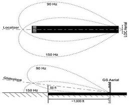
An ILS consists of three independent sub-systems, one providing lateral (left-right) guidance (The localizer), another vertical (up-down) guidance (The glide slope or glide path), and thirdly marker beacons that provide distance to the runway threshold.
THE LOCALIZER
The localizer antenna array is normally located beyond the departure end of the runway and generally consists of several pairs of directional antennas. Two signals are transmitted on one of 40 ILS channels between the carrier frequency range 108.10 MHz and 111.95 MHz (with the 100 kHz digit always odd). The localizer antenna system generates two signals. The two signals have the same carrier frequency but different audio modulating signals. One RF signal is AM modulated with 90Hz and is sent to the left side of the runway. The other RF signal is AM modulated by 150Hz and is directed toward the right side of the approach center line. The ratio of 90Hz to 150Hz modulation, received by the aircraft, drives the left-right localizer display. The RF signals transmitted, by the localizer antenna's, are calibrated such that the 90 and 150 Hz modulation signals are equal strength on a vertical plane extending out from the runway centerline.
In addition to the previously mentioned navigational signals, the localizer provides for ILS facility identification by periodically transmitting a 1,020 Hz Morse code identification signal. This lets users know the facility is operating normally and that they are tuned to the correct ILS. The glide slope transmits no identification signal, so ILS equipment relies on the localizer for identification.
The AV-10 provides a localizer test signal with station ID beep. Two different carrier frequencies are selectable. The AV-10 signal provides for on centerline, left and right of centerline testing as well as the ability to check the NAV flag when no 90Hz and no 150Hz outputs are selected.
THE GLIDESLOPE
A glide slope (GS) or glide path (GP) antenna array is sited to one side of the runway touchdown zone. The GP signal is transmitted on a carrier frequency between 329.15 and 335 MHz using a technique similar to that of the localizer. The centerline of the glide slope signal is arranged to define a glide slope of approximately 3° above horizontal (ground level). The beam is 1.4° deep; 0.7° below the glide slope centerline and 0.7° above the glide slope centerline. The signal consists of two intersecting RF carrier signals. The upper RF signal is 90Hz AM modulated while the lower signal is 150Hz AM modulated. If the aircraft is on the glide path, equal amplitudes of both tones will be received and the deviation bar will be centered. If the aircraft is above the glide path, 90Hz modulation dominates and the cockpit CDI display is displaced downward. If below the glide path, 150Hz modulation dominates and the display is displaced upward. The glide slope RF frequencies are pared with its localizer frequency.
The AV-10 provides a glide slope test signal for on glide path, above glide path, and below glide path. The 90Hz and 150Hz signals can also be selected off for optional glide slope flag testing. The RF frequency is selected from two choices.
THE MARKER BEACONS
On some installations, marker beacons operating at a carrier frequency
of 75 MHz are provided. When the transmission from a marker beacon is
received it activates an indicator on the pilot's instrument panel
and the tone of the beacon is audible to the pilot. The distance from
the runway at which this indication should be received is published in
the documentation for that approach, together with the height at which
the aircraft should be if correctly established on the ILS. This
provides a check on the correct function of the glide slope as well as
providing a waypoint. There are three types of marker beacons. The
outer marker is located at the glide slope intercept point and is a
75MHz RF signal, AM modulated with a 400Hz two dashes per second tone.
The middle marker is located at CAT-I decision-height point and is a
75MHz RF signal, AM modulated with 1300Hz dot-dash. The inner marker
is located at CAT_II decision-height point and is a 75MHz RF signal,
AM modulated with 3000Hz.
An ILS may have 0, 1, 2 or all 3 marker beacons. The signal from the
marker beacon antenna's is designed to provide a narrow vertical
cone signal to the aircraft. The 75MHz marker receiver in the aircraft
is designed with a very low sensitivity (200uV Typical) so that the
marker is only received when the aircraft is above the marker beacon
transmitter location. The AV_10 provides marker beacon test signals,
however since the aircraft marker sensitivity is low and the AV-10
antenna is inefficient at 75MHz, the AV-10 antenna needs to be placed
close to the aircraft marker antenna for reception.
DISTANCE MEASURING PRINCIPLES (DME)
Aircraft use DME to determine their distance from a land-based transponder by sending and receiving two pulses of fixed duration and separation. The ground stations are typically co-located with VORs. The aircraft DME measures slant distance from the aircraft to the DME ground station by determining the time it takes for the signal to travel from the aircraft to the ground station and back. A radio signal requires 6.18 microseconds to travel one nautical mile or 12.36 uS to travel one mile and then back. The ground DME station has a constant 50 uS delay between reception of an interrogation and transmission of the reply. So to determine the distance from the aircraft to the DME ground station, measure the time between airborne interrogation and the DME's reply. Then subtract the 50Us delay and divide by 12.36Us to calculate distance to DME.
The DME ground station transmits at a constant pulse repetition frequency (PRF) of 2700 pulse pairs per second, consisting of random pulses (squitter) and replies to interrogations. The reason that the ground station always transmits is due to the fact that the TACAN system requires the DME pulses to operate. If the DME ground station receives more than 2700 interrogations per second, it will only reply to the 2700 strongest. The airborne DME equipment has circuitry that allows it to find replies to its interrogations. When it has picked out its own replies from the rest of the squitter, and is measuring the distance to the ground station, it is said to be tracking or locked on.
DME frequencies are paired to VHF omnidirectional range (VOR), or ILS frequencies, and a DME interrogator is designed to automatically tune to the corresponding DME frequency when the associated VOR frequency is selected. An airplane’s DME interrogator uses frequencies from 1025 to 1150 MHz DME transponders transmit on a channel in the 962 to 1150 MHz range and receive on a corresponding channel between 962 to 1213 MHz The band is divided into 126 channels for interrogation and 126 channels for reply. The interrogation and reply frequencies always differ by 63 MHz. The spacing of all channels is 1 MHz with a signal spectrum width of 100 kHz.
The X and Y channels differ to the spacing of the individual pulses in the DME pulse pair, 12 US interrogation and reply spacing for X channels and 36uS interrogation 30uS reply double pulse spacing for Y channels.
DME facilities identify themselves with a 1350 Hz morse code three letter identity. If collocated with a VOR or ILS, it will have the same identity code as the parent facility. Additionally, the DME will identify itself between those of the parent facility. The DME identity is 1350 Hz to differentiate itself from the 1020 Hz tone of the VOR or the ILS localizer.
The AV-10 allows an 108.0 MHz VOR frequency with either X or Y channel selection. The 108.00 MHz X channel selection uses 1041 MHz aircraft transmitted 12uS pulse pairs for interrogation, with 978MHz reply 12uS pulse pairs. The 108.05 MHz Y channel selection uses 1041 MHz aircraft transmitted 36uS pulse pairs for interrogation, with 1104 MHz reply 30uS pulse pairs. A constant 20 nautical mile distance is simulated by the AV-10 in both cases.
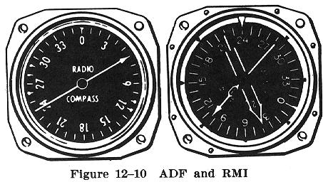
AUTOMATIC DIRECTION FINDER (ADF)
The ADF is one of the older types of navigation that is still a valuable instrument even in today's GPS equiped aircraft. NDB navigation consists of two parts - the automatic direction finder (or ADF) equipment on the aircraft that detects and processes the signal, and the simple low frequency amplitude modulated NDB transmitter.
NDBs used for aviation are standardised to be operated on frequencies between 190 KHz and 1750 kHz, although normally all NDBs in North America operate between 190 kHz and 535 kHz. Each NDB is identified by a one, two, or three-letter Morse Code call sign. The ADF can also locate transmitters in the standard AM radio broadcast band (530 kHz to 1700 kHz at 10 kHz increments in the Americas, 531 kHz to 1602 kHz at 9 kHz increments in the rest of the world). The ADF has direction finding circuitry which result in the bearing indicator always pointing to the station to which it is tuned. That is, when the bearing pointer is on the nose position, the station is directly ahead of the airplane; when the pointer is on the tail position, the station is directly behind the airplane; and when the pointer is 90 degrees to either side (wingtip position), the station is directly off the respective wingtip.
NDB signals and all radio waves (Electromagnetic radiation) consist of electric field and magnetic field waves. These fields are perpendicular in space, and their amplitudes vary sinusoidally with time. NDBs transmit a vertically polarized wave which means the E-field is vertical and the H-field is horizontal.
The SDF receiver has two types of antenna's. One or more Loop antenna's to sense the magnetic field wave and a sense antenna to pickup the electric field wave. All ADF systems have loop and sense antennas. With the older ADF's, they are two separate antennas. The loop antenna is a flat antenna usually located on the bottom of the aircraft, while the sense antenna is a long wire that often runs from top of the tail to the top of the of the cabin. More recent ADF's have a combined loop/sense antenna.
To explain the operation of the ADF receiver. Assume that it has a square coil of wire that is its loop antenna. Lets assume that it can rotate the loop such that the coil faces the transmitter. The magnetic field wave will induce voltages in each of the 4 sides of the loop that counteract opposite sides thus no current flow will occur. Now if the coil is rotated 90 degrees, the magnetic wave will arrive at one side of the coil before the opposite side thus the phase difference will induce a current flow in the loop. If the loop is then rotated 180 deg the opposite current will be induced in the coil, which also producing a signal maximum. To determine which of the two loop antenna maximums is the one pointing to the station, the signal from the sense antenna, that reads the electric field, is used to provide the reference field. One loop max current will be inphase with the electric field while the other loop max current will be out of phase.
The AV-10 will generate a low frequency signal at 400KHZ, 450KHz, 650KHz or at 1200KHz. The low level, aprox -10dbm, signal is AM modulated by an aprox 500Hz tone beep at about 1HZ rate. The signal is useful for testing the ADF reception. It, or any other signal source, is not very useful for checking the direction finding ability of the ADF receiver. The reason is all about NEAR FIELD and FAR FIELD electromagnetic radiation.
As we have indicated, there are two types of antenna's. Those that produce or sense electric fields and those that produce or sense magnetic fields. However any antenna will create both an electric and magnetic field. Close to the antenna an electric antenna will have a strong electric field and a weak magnetic field. Moving away from the antenna the magnetic field will become stronger (relative to the electric field) and from a certain distance on the ratio between both fields will become constant. A magnetic antenna will have strong magnetic field and weak electric field near the antenna, but further away the electric field will become relatively stronger until the ratio of both fields again becomes constant. At this point both fields form together the electromagnetic field, they are coupled and cannot exist independently from each other. In fact their ratio defines the impedance of free space and is about 377 ohms.
Near field : area close to the antenna. The electric
and magnetic fields are not coupled and the radio of their strength
primarily depends on the distance from the antenna.
Far field : area at sufficient distance from the
antenna. The electric and magnetic fields are coupled and at a
constant ratio.
As can be seen from the above graph, for both electric and magnetic waves to exist in a reasonable relationship one needs to be at least .16 wavelengths from the transmitter. At 0.16 wavelengths both fields will be equal and some sources let the far field start from here. But in practice it is recommended to use a distance of at least 0.5 wavelengths for accurate field strengths. Well at 500 KHz one half wavelength is 1000 feet. So while a test signal is handy to see that the ADF receiver is able to pickup the NDB. To check the ADF's direction finding accuracy, its probably best to do that in the air where near field and reflections aren't an issue.
TRANSPONDER PRINCIPLES
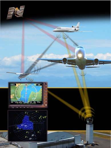
MODE A/C TRANSPONDERS:
Primary radar uses a network of ground stations to locate aircraft. A narrow pulse radio signal transmitted in a narrow beam travels through the air and strikes an aircraft then some of the signal reflects back to the same antenna being used in receive mode. By measuring the elapsed time between pulse transmission and reception, and measuring the directional antenna's angle, allows the target to be located on a 2 dimensional polar display, with the radar antenna at the center. This air traffic control display is called a plan position indicator, or PPI. The PPI display needs two more bits of information. The aircraft altitude and its identification. Secondary radar provides those two bits of information.
Secondary radar is more appropriately a communication system, rather than radar. It requires equipment in the aircraft that receives and responds to pulse encoded transmissions. Secondary radar is associated with the Air Traffic Control Radio Beacon System, or ATCRBS (pronounced "at-crabs"). The transponder in the aircraft receives two major types of pulse amplitude modulated (PAM) interrogations at 1030MHz from ATC. The receipt of a valid interrogation causes the aircraft transponder to reply with one of two types of PAM data at 1090MHz. The first is the mode A squawk identity code and the second is the mode C pressure altitude reply. While sending either of the above replies it can also send an IDENT bit that causes special ATC display handling.
The transponder is connected to an encoding altimeter or "blind encoder". During mode C replies, altitude is encoded using a 11 bit Gilham code allowing for -1000 to 126,700 feet with 100 foot resolution. The following is how the AV-10 decodes the mode C Gilham coded altitude data for display as pressure altitude in feet on its LCD.
*
* DO MODE C ALTITUDE DECODE
*
* calculate altitude from mode C ABCD octal code
* altitude is in a modified Grey code "GILHAM" FORMAT
* read in ABCD altitude octal code as A4 A2 A1 B4 B2 B1 C4 C2 C1 D4 D2
D1 from transponder
* then form bit reversed DAB as D1 D2 D4 A1 A2 A4 B1 B2 B4
* then start with a cleared 16 bit variable BDAB
* with [n] n being the bit position, with n=0 at far right
* then do Grey convert on DAB to form BDAB[n] = BDAB[n+1] (+)
DAB[n] : (+) is exclusive or
* now BDAB is 0 0 0 0 0 0 0 b8 b7 b6 b5 b4 b3
b2 b1 b0
* C = C4 C2 C1 and IF BDAB b0=0 THEN C = C1 C2 C4 {bit rev
C if lsb of BDAB is 0}
* THE VALUE IS LOOKED UP AS:
* IF C=001 THEN LET C=0
* ELSE IF C=011 THEN LET C=1
* ELSE IF C=010 THEN LET C=2
* ELSE IF C=110 THEN LET C=3
* ELSE IF C=100 THEN LET C=4
* ELSE ERROR
* FINALLY ALTITUDE/100 = (BDAB * 5) + C - 12
*
*
The Gilham code has a unique characteristic in that only one bit changes between subsequent values.
The AV-10 allows for testing of the aircraft transponder. It can be set for mode A and mode C testing. Side lobe suppression can be enabled to check that transponder function and IDENTIFY active is displayed. The AV-10 also has a command to measure the aircraft transponders transmit frequency.
A Simplified formula (Friis transmission equation) for path loss
between two isotropic antennas in free space is.
Loss = 20 LOG [ 4*PI*D / L ] D=distance between antennas, L=wave
length of carrier wave, PI is 3.14159.
For transponder at aprox 15 foot from aircraft the formula predicts
about 47 dB loss.
From the AV-10's -10dBm output power and antenna losses; -60 DBm
or less at the aircraft txpdr is reasonable to expect. Allowing that
nominal sensitivity of a transponder is -72dBm. Therefore the receive
sensitivity of the aircraft transponder is inherently roughly checked
during AV-10 testing.
In a similar manner, 100 watt output power from the aircraft transponder is +50dBm. Given 47 dBm transmission loss and -3 antenna loss the signal received by the AV-10 is about 0 dBm. Therefore the av-10's receive sensitivity was designed at about 0 dBm so that transmitter power is also roughly checked during AV-10 testing.
Mode-S TRANSPONDERS and ADS-B:
Mode-S transponders operate on the same 1030 MHz and 1090 MHz frequencies as the old atcrbs units do. Mode S transponders provide all the functionality of an A/C atcrbs transponder plus selective addressing so that ATC can talk to one aircraft without any other aircraft responding. Every registered aircraft is supplied a unique ID by its country. In the US the ID can be found on the FAA web-site. Except for the Mode-A/C/S ALL-CALL, The Mode-S interrogation is designed such that it automatically disables the atcrbs reply.
The AV-10 provides a Mode-A/C/S all-call function as well as a Mode-S ONLY all-call command. Rather than returning a squawk code or altitude the Mode-S unit will send its unique ID code using a S type reply. The AV-10 displays the Hex ID code as well as the cyclic error check code which is all 0’s for a good reply.
Automatic Dependent Surveillance-Broadcast (ADS-B) is a surveillance technology for tracking aircraft as part of the Next Generation Air Transportation System (NextGen). The United States will require the majority of aircraft operating within its airspace to be equipped with some form of ADS-B Out by January 1, 2020. ADS–B consists of two different services: ADS–B Out and ADS–B In. ADS–B Out periodically broadcasts information about each aircraft, such as identification, current position, altitude, and velocity through an onboard transmitter. ADS–B Out provides air traffic controllers with real-time position information that is, in most cases, more accurate than the information available with current radar-based systems. With more accurate information, ATC will be able to position and separate aircraft with improved precision and timing. ADS-B In is the reception by aircraft of FIS-B and TIS-B data and other ADS-B data such as direct communication from nearby aircraft.
The AV-10 can receive the following ADS-B transmitter squitter.
- Mode-S ID Squitter.
- Mode-S Aircraft tail number
- Mode-S Aircraft GPS location Squitter
Using the AV-10, correct operation of Aircraft Terrestrial navigation and the new transponder systems can be assured. We at Sun Avionics hope that the AV-10 will prove to be one of your most effective pieces of avionics test equipment.